Selecting the Tools,Options Command from the main menu, or the Options Button on the Toolbar, will open the Options dialog box. The following tab sheets are available in the dialog box to set various options.
Group |
Field |
Field Description |
Data Library |
Update Data Library |
If Enabled, the data dictionary will be updated should there be a data mismatch between the Dictionary & the project. |
Warn on Data Library Conflicts |
If Enabled, a warning message will appear if there is a data mismatch between the Dictionary & the project. |
|
Use Data Server |
If Enabled, Specify the Multi-user Database Server to use. |
|
Path |
The default data dictionary file, to be used when PowaMaster is executed. |
|
Limits |
Voltage Maximum Limit & Colour |
Is the value whereby if any Bus's voltage is above this value, the colour will be changed to the colour chosen to represent the over-voltage condition. |
Voltage Minimum Limit & Colour |
Is the value whereby if any Bus's voltage is below this value, the colour will be changed to the colour chosen to represent the under-voltage condition. |
|
Conductor Rating A warning & Colour |
Is the percentage value whereby if any Branch's normal rating is exceeded by this value, the colour will be changed to the colour chosen to represent the overloaded condition. |
|
Conductor Rating B warning & Colour |
Is the percentage value whereby if any Branch's overload rating is exceeded by this value, the colour will be changed to the colour chosen to represent the overloaded condition. |
In order for the User to rapidly obtain feedback as to element parameters and results, PowaMaster allows the User to display element properties and results next to the element. The User can specify the font to use to display this detail and can also select what parameters are to be displayed. The global display options are set for each element type in the Options\Display. Select the tab-sheet of the appropriate element type e.g. busbars, branches etc.
|
For each element type, the User can select to toggle the display of the text. The User specifies the parameters to display by clicking on the buttons on the left of each corresponding check-box. The check-boxes must be toggled accordingly to specify the number of parameters to be displayed. The number of parameters that can be displayed is limited by the number of check-boxes. |
In addition to the global display options, the User can customise the display settings of individual elements in the network. This is achieved by editing the element, selecting the display tab-sheet, setting the display options and Checking the "Force Local Text Display". If this is not checked, then the global display options will be applied to the element regardless of the elements customised display options.
Display |
Field |
Field Description |
General |
Font |
The Main Font that is used on the worksheet. |
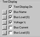
Text Display On |
If enabled the user will be able to select what information is to be displayed for each item in the chosen display font. If disabled, only the graphical symbol is displayed. |
|
Direction Arrows On |
If Enabled an Arrow will indicate the Direction of the Active Power Flow. |
|
Snap Size |
If Enabled the mouse will snap to the specified grid snap size |
|
Grid Size |
If Enabled a Grid will be displayed |
|
Units |
Distance in mi |
If enabled, Distances will expressed in miles else in km. |
Temperature in °F |
If enabled, all temperature will be expressed in Degrees Fahrenheit else in Degrees Celsius. |
|
Scale 1: |
The scale-enabled facility will normally be used where nodes are placed on a bitmap background and the conductor distance should conform to the ground distance.
If the scale is enabled, the Scale 1:x, where the user chooses x, will be used to determine the distance between two points. |
|
Element Display (Busbar, Branch, etc.) |
Text Display On |
If enabled the user will be able to select what information is to be displayed for each Bus Bar. |
Display Options |
Up to 5 Fields can be selected to be displayed for each busbar. See Also:
Up to 3 Fields can be selected to be displayed for each series element. See Also:
Up to 2 Fields can be selected to be displayed for each Shunt Element. See Also: |
|
Name Prefix |
Prefix to use to enable unique Names |
|
Name Suffix |
Suffix to use to enable unique Names |
Group |
Field |
Field Description |
Calculation |
Enable Automatic Tap Change |
If Enabled, it allows Transformers to automatically adjust the tap changer to be within its control voltage window if the Transformer allows automatic tap changing. |
Maximum Iterations |
Maximum number of iterations allowed |
|
Iteration Tolerance |
Minimum Power Mismatch Tolerance to converge. |
|
Power Base (MVA) |
Base MVA for the study |
|
Fundamental Frequency |
Fundamental Frequency for Harmonic Studies |
|
Fault Calculation |
Use Voltage Factor (pu) |
Specifies the per unit voltage to use for fault level calculations. |
Use Bus Angle |
When checked, includes the bus voltage angle in fault calculations. |
|
Use Calculated Bus Voltage |
The load flow voltage results are used in the calculation of fault levels. |
|
Use Time Delay Factor (s) |
Used to determine the generator short circuit decay factor. |
|
Include Device Fault Contribution |
If checked the device fault contribution will be used in Fault level studies. |
|
Source Defaults |
Specify the defaults to use when specifying the source fault level in current or impedance. |
|
Sub Transient State |
Fault Currents are based on Sub Transient impedances |
|
Transient State |
Fault Currents are based on Transient impedances |
|
Steady State |
Fault Currents are based on Steady State impedances |
|
Fault Contact Resistance |
Fault Contact Resistance to use in Fault Calculations |
|
Earth Electrode Resistance |
Earth Resistance to use in Fault Calculations |
|
Calculation Method & Acceleration Factors |
Gauss-Seidel |
Acceleration factors are applied to the voltage error from each successive iteration. Typical values should be between 0 - 0.5 |
Newton-Rhapson |
α - Scales the change in voltage magnitude. β - Scales the change in voltage angle. Typical Values (α = 0.5 to 1 and β = 0.5 to 1) |
|
Fast De-Coupled Newton Rhapson |
α - Scales the change in voltage magnitude. β - Scales the change in voltage angle. Typical Values (α = 0.1 to 0.6 and β = 0.1 to 0.4) |
The user can define a report using the available fields on the Tools/Options/User Report Page. Report Fields can be individually selected for Busbars, Branches and Transformers.
Multiple fields can be selected and moved to the Report Fields Box. The order of how the fields appear in the report can also be changed using the Move buttons.
The user must specify the fields for the report before selecting the View, Report command from the main menu. The user will now be able to generate a Report of the complete network.
This User Report can also be exported to a Text file or to Excel for further analysis. Templates for the parameters to be displayed in the User reports can be imported or exported and saved as a text file.